GAPS time of flight DRS4 sampling board
Low power, high bandwidth, GS/s DAQ board
While half the battle is getting the preamp to meet timing requirements, the other half is putting together a board and digital back end that far exceeds 500 ps resolution and is capable of handling the large amount of data generated in real time.

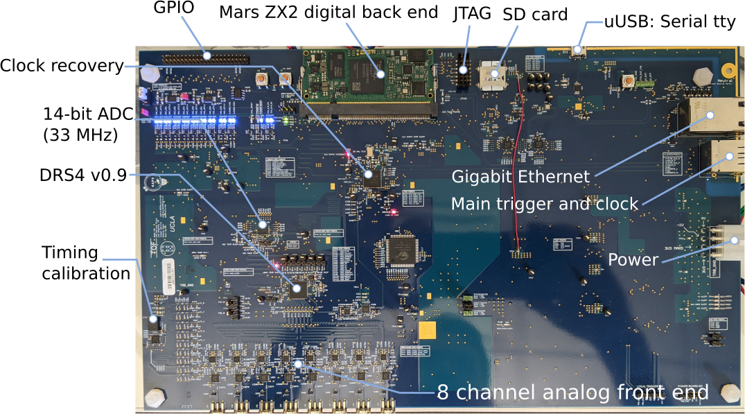
Working with three engineers I lead and contributed to the design of a custom DRS4 (switched capacitor array ASIC) based sampling board.
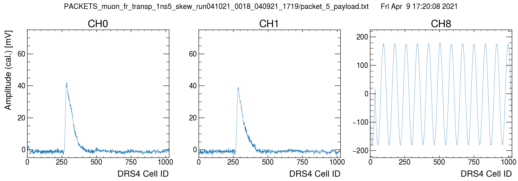
Single ended analog inputs are buffered by instrumentation op-amps whose differential outputs are sampled by the DRS4. The input stage also includes high isolation RF switches to choose between SMA inputs or an onboard 25 MHz TCXO used for timing calibration.
The DRS4 is a dense, low power and high performance part. The SCA behaves as a “time-stretcher”, buffering a faster analog signal (muon pulses are about 100 ns wide) in a domino wave that can then be clocked out at lower speeds by a more affordable 40 MS/s ADC.
Control of the ASIC and data acquisition is done on the PL fabric of a Zynq-7 with custom firmware written by our group. A DMA engine was developed to write data packets directly into a 128 MB system RAM buffer. Of the many benefits of using the Zynq, easy memory management, and access to memory mapped I/O has to be near the top of the list. Software handles draining the RAM and transfering to a central computer over a gigabit network.
For peripherals we opted for I2C and perhaps went a little overboard on the number of sensors. We monitor five board temperature locations, magnetic field, humidity/pressure, along with voltage and current information for over half a dozen supply rails.
